
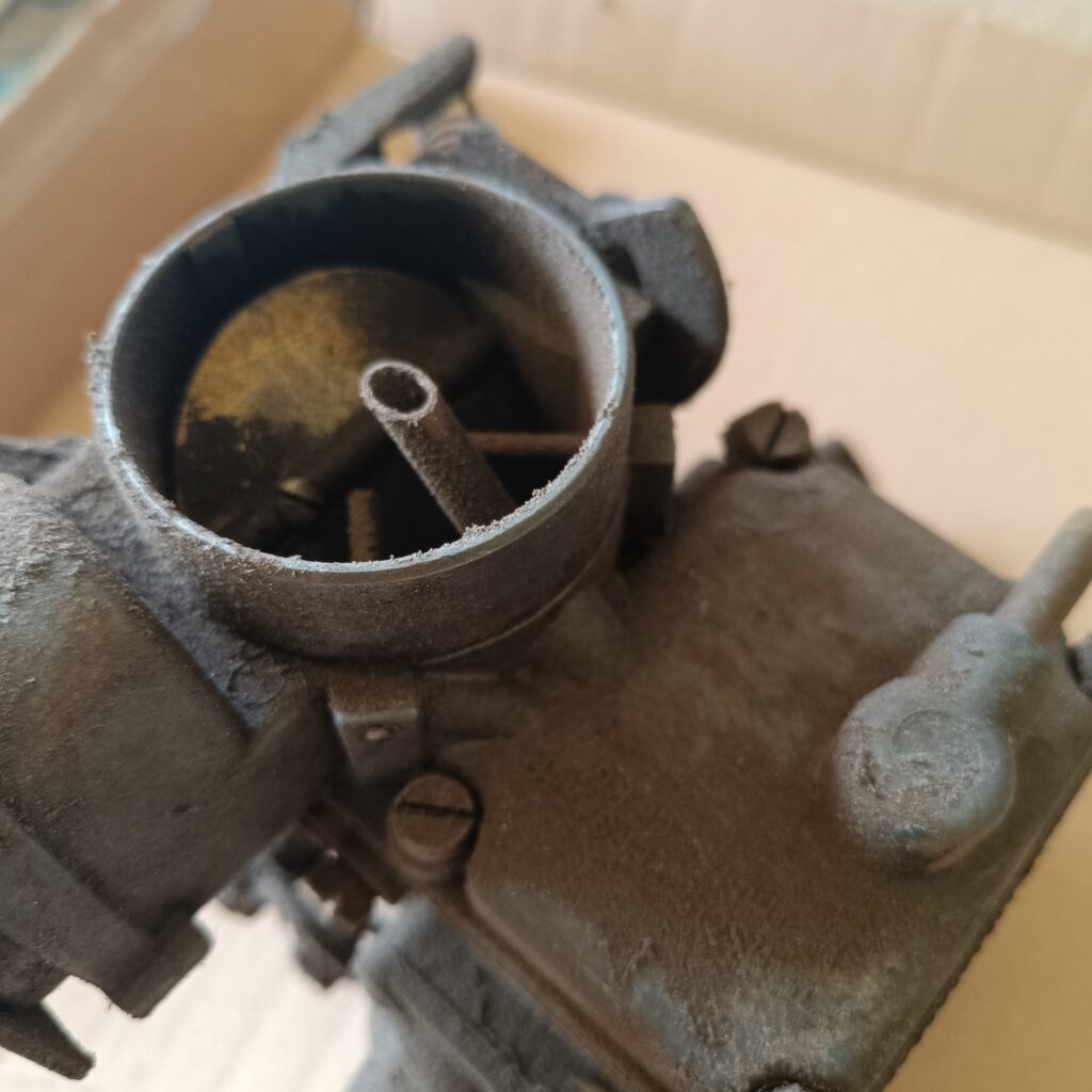
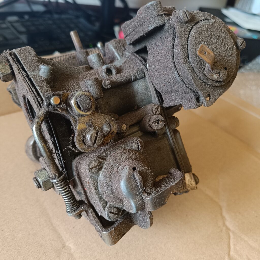
In this issue, we will service a standard Solex carb. Specifically, this one is a Solex 34 PICT3, but the process is very similar for any of the Solex carbs, either single or dual.
Purchasing
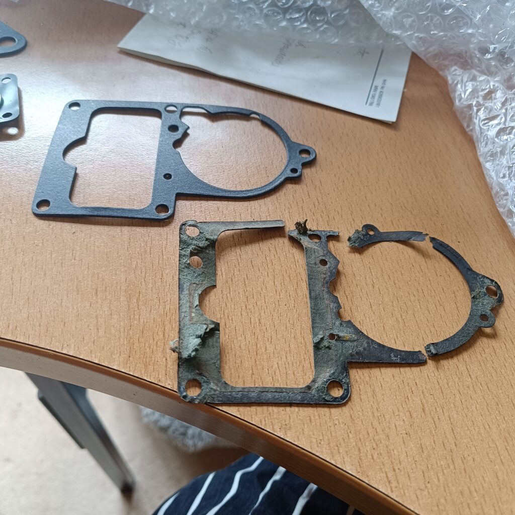
Rebuild kit – go to your favourite online store of choice and purchase the Solex carb repair kit, these are available for around £20 at time of going to press. Note, the kit contains the rebuild parts for many sizes of Solex carb, meaning that you will not use all items in the bag! It also usually includes instructions!
Cleaner – Unless you have something else suitable, you should also get a can of carb cleaner. A 400ml can is under £5 and will be sufficient for the task. This should be done in a well ventilated area / outside as carb cleaner is not pleasant and is suspected to be carcinogenic.
Tools
Soft brush (eg toothbrush) – optional
Metal or glass pots for holding parts as they soak, with lids
Medium and small screwdrivers
11mm, 13mm and 14mm sockets
Needle nosed pliers
Pencil
Removing
Remove original oil bath air cleaner or after-market air filter. Detach fuel hose and clamp / seal (I use a golf tee peg and cling film), vacuum hose of dashpot (where applicable), and vacuum hose. Disconnect automatic choke cable, bypass air cut-off valve cable (where applicable), and electro-magnetic pilot jet cable. Detach accelerator cable at throttle valve lever and ensure that you tie it off otherwise it pops into the cable channel and disappears. I use a clothes peg to hold where the cable disappears into the fan shroud. Remove two nuts on intake manifold and lift off the carburettor.
Disassembly
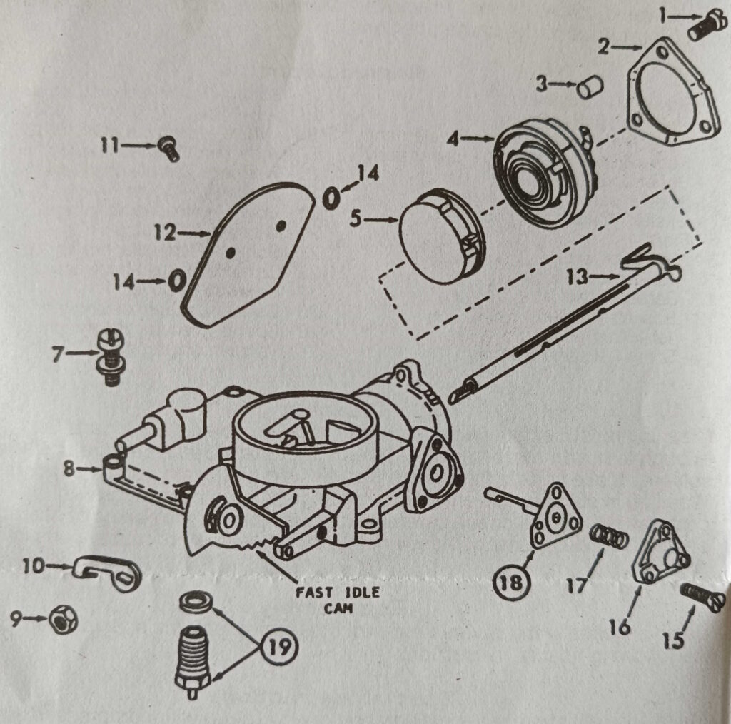
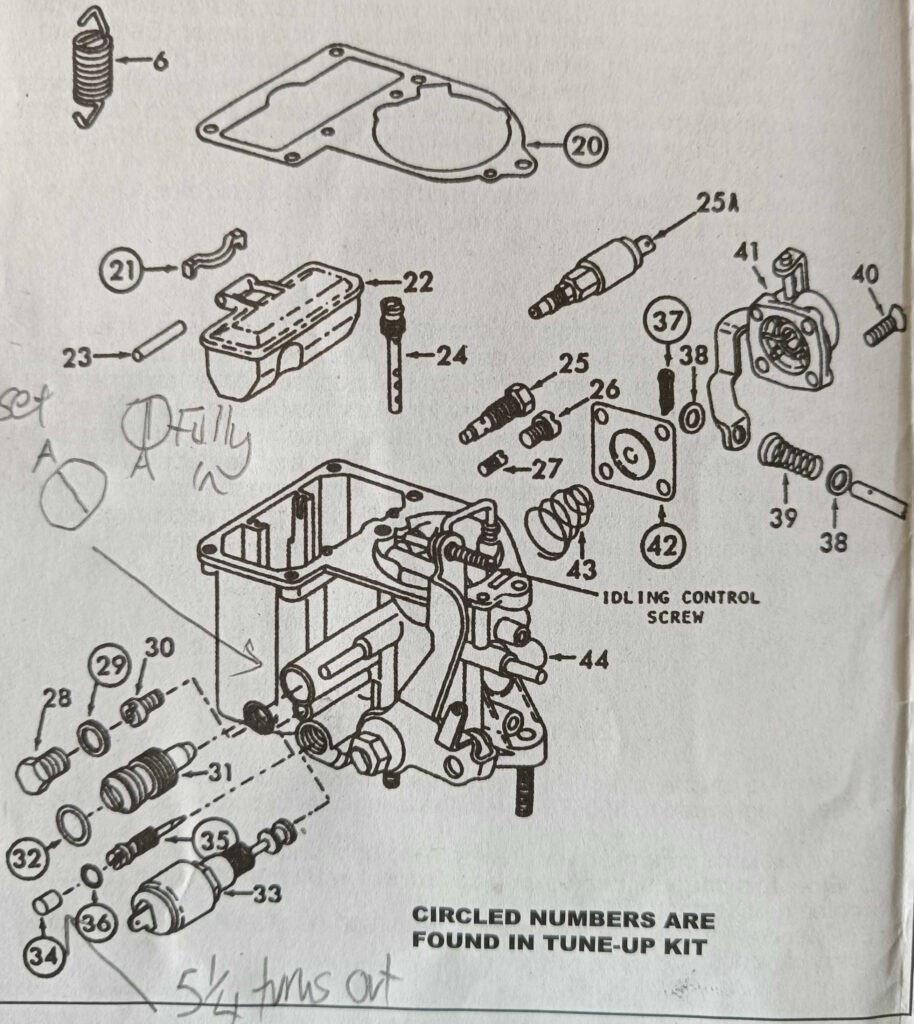
Use exploded view as a guide only.
Carb parts list
1 – Screw (3) – Retaining ring
2 – Retaining ring – Cover
3 Cover with spring and heater element
4 Screw & lock washer (5) – Upper body
5 upper body assy.
6 Needle, seat & gasket assy.
7 Gasket Carburettor
8 – Float
9 – Pin Float lever
10a- Jet Air correction
11 Carrier Main jet
12 Gasket — Carrier
13 Jet- Main
14 Screw Volume control
15 – Spring – Volume control screw
16 – Jet – Pilot
16A – Valve Idling cut0ff (30PICT -1 only)
17 – Nut – Throttle shaft lever
18 – Washer – Throttle shaft lever
19 – Screw (4) – Cover
20 – Cover – with lever & linkage
21 – Diaphragm – Pump
22 – Spring – Pump diaphragm
23 – Carburettor main body assy.
24 – Screw (3) – Cover
25 – Cover – Vacuum diaphragm
26 – Spring – Vacuum diaphragm
27 Vacuum diaphragm – Choke
Cleaning
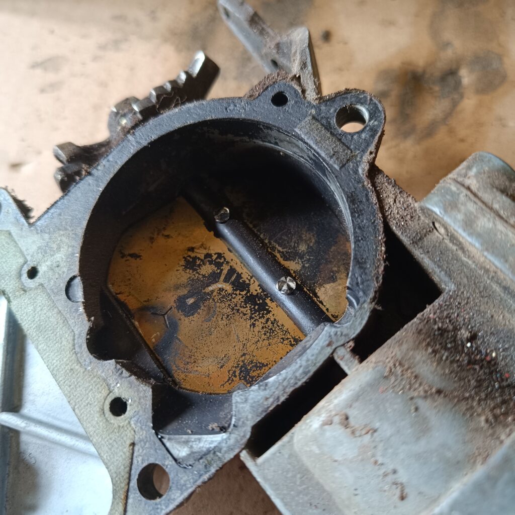
Cleaning must be done with carburettor disassembled, soak parts long enough to soften and remove all foreign material, Use a carburettor cleaning solvent. Make certain the throttle body is free of all hard carbon deposits, wash off in suitable solvent. Blow out all passages in castings with compressed air and check carefully to insure thorough cleaning of obscure areas. Caution: do not soak solenoids, switches, float, or rubber parts in solvents.
Instructions
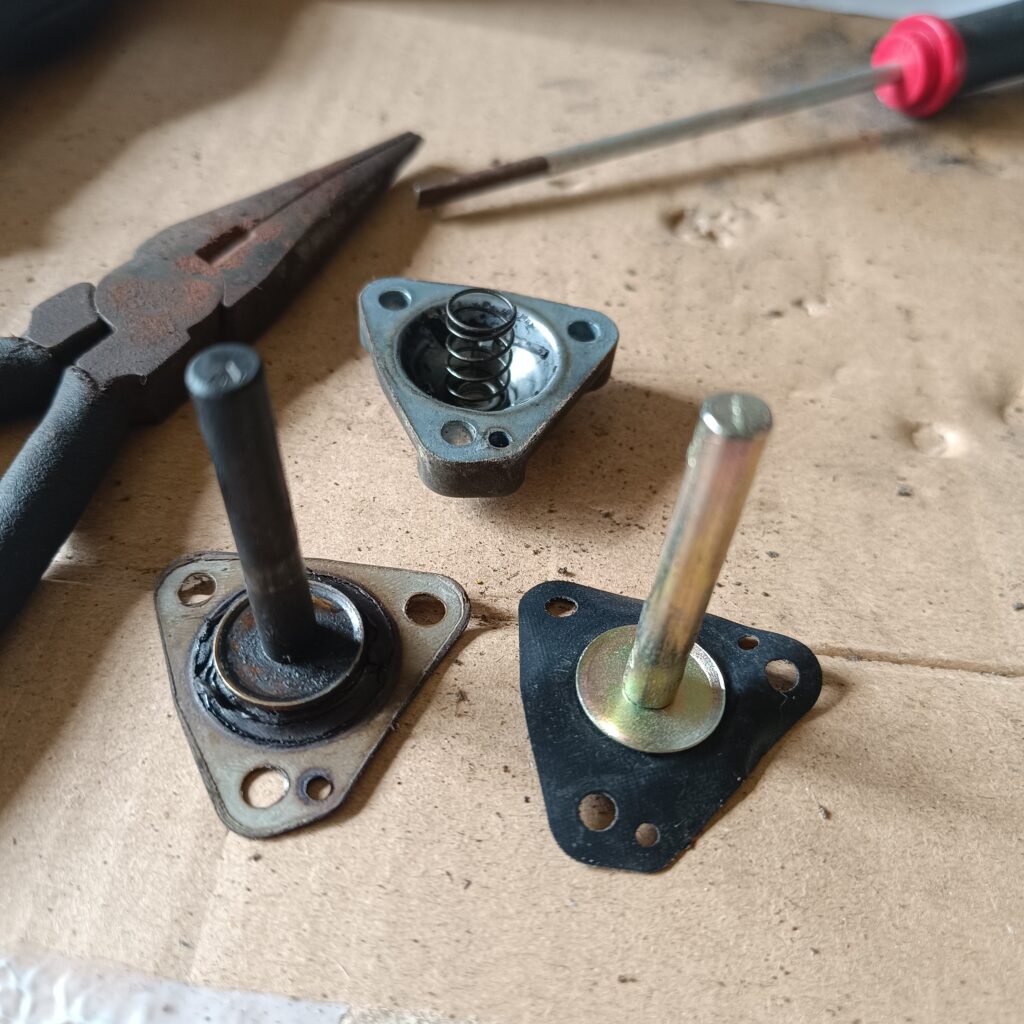
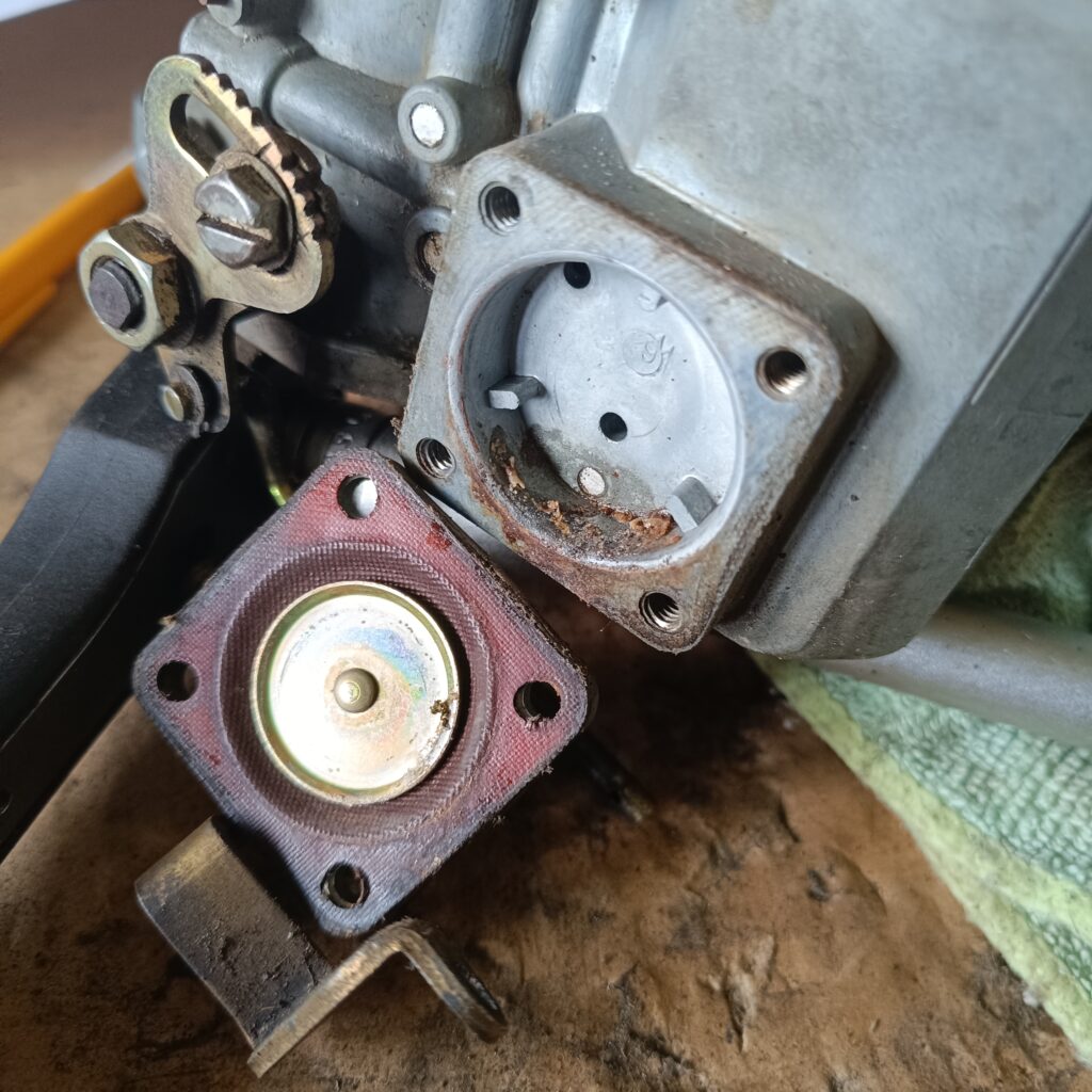
Make sure all jets are clean and open. Clean with compressed air, not wires or pipe cleaners. When installing the pump diaphragm and spring (22) make sure the larger end of spring is properly seated in the carburettor body cavity. Be sure to install the diaphragm (21) with plunger toward pump cover (20). Check for a worn spot (Depression) on the float lever where it contacts the fuel inlet needle valve, replace float assembly, if necessary, float assembly may be purchased at your local VW dealer, P/N 111-129-391A-Round Shaped Float. A proper needle seat gasket must be used for specific carburettor. Use the following chart to determine the correct gasket.
Carburettor model
28 PICT-I. -2 1.0 MM .040″
30 PICT-I 1.0 MM .040″
Check the thermostatic spring in housing (Item #3) for damage. If it is distorted or “kinked,” replace the assembly. Also, make sure the electrical heating element is not broken, This can be checked with an ohmmeter or connected to a correct voltage battery for a few minutes to see if it warms up.
(Be sure to ground the inside metal part of the housing to complete the circuit). When installing assembly with spring and heater element, carefully rotate assembly counterclockwise, being sure the hook-on coil end engages with the lever on choke shaft. Continue rotating approximately 1/8 – turn more until index marks align. Then tighten screws securely.
Installing
Install in reverse order of removing. Torque retaining nuts to 2.0 MKG. (14 Ft Lb.)
Idling Adjustment
28 PICT, -1, -2. 30 PICT -1, -2.
A. Warm up engine; check if the automatic choke is fully open.
B. Set idling speed to 850 RPM with the idling control screw (See exploded view).
C. Turn volume control screw (Item #14) to right until speed starts to drop.
D. From this position, turn volume control screw (Item #14) to the left until engine runs fastest.
E. If necessary, regulate the engine speed (800-900 RPM) again with the idling control screw.