Category Archives: Technical

Items of a technical nature relating to mechanical, electrical or bodywork issues

Ask The Mechanic – 171 – E10 fuels

The mechanic has noticed a recent uplift in questions and concerns surrounding the upcoming introduction of E10 fuels. The following is information provided by the Federation of British Historic Vehicles Clubs that we hope members will find useful. Federation of British Historic Vehicles
Clubs – Introduction of E10 petrol After an extensive consultation process, the Department for Transport has announced that they will legislate to introduce E10 petrol as the standard 95-octane petrol grade by 1 September 2021. They will also require the higher-octane 97+ ‘Super’ grades to remain E5 to provide protection for owners of older vehicles. This product will be designated as the ‘Protection’ grade.
The introduction of the 95-octane E10 grade and the maintenance of the Super E5 protection grade will be reviewed by the Government after 5 years to ensure they remain appropriate to the needs of the market:
In relation to the E5 protection grade, such a review will examine market developments over the period.
HM Government have sought to reassure FBHVC members and historic vehicle owners that, without
a suitable alternative becoming available, it is highly likely the Super E5 protection grade would continue
to be available. Filling stations that stock 2 grades of petrol and supply at least one million litres of fuel in total each year will need to ensure one product is the Super E5 protection grade. While not all filling stations meet these criteria, almost all towns across the UK will have a filling station that supplies the ‘Super’ grade and currently one major retailer, a national supermarket group, has committed to offer the product. The main exception to this is in certain parts of the Highlands, north and west coast of Scotland, which will be covered by an exemption process and allowed to continue to market the 95-octane E5 grade. The Federation therefore recommends that all vehicles produced before 2000 and some vehicles from the early 2000s that are considered non-compatible with E10 – should use the Super E5 Protection grade where the Ethanol content is limited to a maximum of 5%. To check compatibility of vehicles produced since 2000, we recommend using the new online E10 compatibility checker: https://
www.gov.uk/check-vehicle-e10-petrol . It should be noted that some Super E5 Protection grade products do not contain Ethanol as the E5 designation is for fuels containing up to 5% Ethanol. Similarly E10 petrol can contain between 5.5% and 10% ethanol by volume.

Product availability varies by manufacturer and geographical location and enthusiasts should check the situation in their location.


Latest News:
The federation’s fuels specialist Nigel Elliott has received some new questions with regards to
ethanol and the use of E10 in historic vehicles and his thoughts are as follows:
There are three key areas of concern with Ethanol compatibility with historic and classic vehicle fuel
systems:
‹ Corrosion of metal components
‹ Elastomer compatibility – swelling, shrinking and
cracking of elastomers (seals and flexible pipes)
and other unsuitable gasket materials
‹ Air/fuel ratio enleanment
Corrosion of metal component
Ethanol has increased acidity, conductivity and inorganic chloride content when compared to
conventional petrol which can cause corrosion and tarnishing of metal components under certain
conditions. These characteristics are controlled in the ethanol used to blend E5 and E10 European and UK petrol by the ethanol fuel specification BS EN15376 in order to help limit corrosion. Corrosion inhibitor additives can be very effective in controlling ethanol derived corrosion and are recommended to be added to ethanol in the BS EN15376 standard. It is not clear if corrosion inhibitors are universally added to ethanol for E5 and E10 blending so as an additional precaution it is recommended that aftermarket corrosion inhibitor additives are added to E5 and E10 petrol. These aftermarket ethanol corrosion inhibitor
additives often called ethanol compatibility additives are usually combined with a metallic valve recession additive (VSR) and sometimes an octane booster and have been found to provide good protection against metal corrosion in historic and classic vehicle fuel systems.
Elastomer compatibility
As the ethanol molecule is smaller and more polar than conventional petrol components, there is a lower energy barrier for ethanol to diffuse into elastomer materials. When exposed to petrol/ethanol blends these materials will swell and soften, resulting in a weakening of the elastomer structure. On drying out they can shrink and crack resulting in fuel leaks. Some aftermarket ethanol compatibility additives
claim complete protection for operating historic and classic vehicles on E10 petrol. The FBHVC is not aware of, or has tested any additives that claim complete fuel system protection with respect to elastomer and gasket materials for use with E10 petrol. The FBHVC therefore recommends that elastomer and gasket materials are replaced with ethanol compatible materials before operation on E10 petrol.
Air/fuel ratio enleanment
Ethanol contains approximately 35% oxygen by weight and will therefore result in fuel mixture enleanment when blended into petrol. Petrol containing 10% ethanol for example, would result in a mixture-leaning effect equivalent to approximately 2.6%, which may be felt as a power loss, driveability issues (hesitations, flat spots, stalling), but also could contribute to slightly hotter running. Adjusting mixture strength (enrichment) to counter this problem is advised to maintain performance, driveability and protect the engine from overheating and knock at high loads.
Modern 3-way catalyst equipped vehicles do not require mixture adjustment to operate on E10 petrol
because they are equipped with oxygen (lambda) sensors that detect lean operation and the engine
management system automatically corrects the fuel mixture for optimum catalyst and vehicle operation.
Operating classic and historic
vehicles on E10 petrol If you should decide to make the necessary vehicle fuel system modifications together with the addition of an aftermarket additive to operate your classic or historic vehicle on E10 petrol. The FBHVC strongly recommends that you regularly check the condition of the vehicle fuel system for elastomer and gasket material deterioration and metallic components such as fuel tanks, fuel lines and carburettors for corrosion. Some plastic components such as carburettor floats and fuel filter housings may be become discoloured over time. Plastic carburettor float buoyancy can also be affected by ethanol and carburettors should be checked to ensure that float levels are not adversely affected causing flooding and fuel leaks.
Ethanol is a good solvent and can remove historic fuel system deposits from fuel tanks and lines and
it is advisable to check fuel filters regularly after the switch to E10 petrol as they may become blocked
or restricted. If your vehicle is to be laid up for an extended period of time, it is recommended that the
E10 petrol be replaced with ethanol free petrol which is available from some fuel suppliers. Do not leave
fuel systems dry, as this can result corrosion and the shrinking and cracking of elastomers and gaskets as
they dry out.
Spares by Ian Crawford

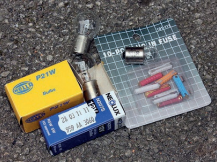
Many people will be away and wish they had something with them – here is a list from club member Ian Crawford on spares he packs in his 1971 Bay window that he bought at 1 year old in 1972. I am not sure about corks – leftover wine is not something I really understand!

Parts
• Accelerator Cable
• Aluminium Tube (To Fit Inside Fuel Hose If Leaking)
• Battery Earth Strap
• Brake and Clutch Fluid
• Brake Pedal Return Spring
• Spare Bulbs
• Cable Ties (Various Lengths)
• Carburettor Return Spring
• Clutch Cable
• Coil
• Condenser For Distributor (Make Sure You Have The Correct “Bung”!)
• CV Axle Boot Cap and Grease
• Distilled Water
• Distributor Cap and Rotor Arm x2
• Distributor Contact Points
• Dynamo Brushes
• Engine Oil (5 litres)
• Fan Belt x2
• Fuel Hose and Clips
• Various Fuses
• Handbrake Cable
• Rocker Cover Gaskets x2
• Spark Plug Set
• Starting Relay and Fuse
• Tyre Valve Cores
• Voltage Regulator
• Walking Boot Laces

Tools
• Allen Keys
• Battery Diagnostic Tester
• Feeler Gauges
• Hacksaw Blades
• Insulation Tape
• Magnetic Dish Holder
• Magnifying Glass (My Eyes Are Dimming!)
• Multi Meter and Spare Battery
• Plastic Wire Cutters
• Pill Pot Containing Matches, Lighter, Flints, Water Purification Tablets, Sweeteners, Sewing Kit, Safety Pins and Buttons.
• Shorting Links
• Stanley Knife
• Tyre Pressure Gauge
• Vaseline
• Wine Corks
• Other Various Tools
Ian has provided a pretty extensive list here, very cautious!
We would also recommend a timing gun if space allows, a foot pump, warning triangle, decent jack, various sockets and spanners and maybe even a fuel pump! (We even carried a spare carburettor once!)
Thanks to Ian for his submission, hopefully this will help members when putting a kit together.

Ask The Mechanic – 169 – Solar Panel Charge Controllers

For this instalment of The mechanic, we welcome a submission from the club’s chairman;
Malcolm Marchbank.
SR PWM MPPT – A question of control

If you have or thinking of getting a PV (photo voltaic) solar panel, then these terms may concern you.
There have been several articles about the use of solar panels to provide power in vans when there
is no hook up available. The panel(s) will almost certainly be used to charge a battery for use when
there is insufficient power available from the sun. The maximum power available from any panel is in a very clear set of circumstances, the sun needs to have an energy at the panel of 1000 watts per square meter, the sun’s rays must strike the panel perpendicularly, the air temperature should be 23 deg C. So, if you set up your panel at noon on a cloud free midsummer’s day carefully angled so the sun strikes it at 90 deg and there is a gentle breeze, a 100w rated panel will give 100w of electrical power. In any other circumstances the power will be substantially less. So, in reality it is better to estimate the average power to be 30 to 60w from a 100w panel.
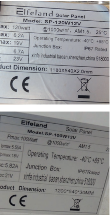
The next thing is how to make the most of the power we do get. If you examine the “rating plate” fitted to almost all solar panels you will see some numbers. Ok you see 100w max power but look at the “ipmax”
this is the current at maximum power, ”vpmax” this is the voltage at maximum power. A typical example
of a 100w panel ip max =5.55a vp max =18v 185.55 =100w. So we need a control unit to regulate the power sent to the leisure battery. Small panels less than about 30cm square sold as “trickle chargers” to maintain a battery while laying on the dashboard have so little power they are self regulating (SR) as the current is so small as never to damage the vehicle battery. Those for phone or device charging rely on the internal battery controller in the device to regulate the power and prevent overcharging of the internal battery. This leaves the choice of the two types of actual control unit PWM (pulse width modulation) or MPPT (maximum power point tracking). At first the generally available controllers were all PWM and cost from £8 up to around £35. These work by monitoring the battery voltage and sending pulses of power to provide an average voltage to the battery. Initially when the battery is low, the power pulses are very wide, but as the battery voltage rises then the pulse width is reduced. It is important then for the controller to “know” when the battery is at full charge so the pulses can be reduced. Different (lead acid) batteries fall into at least 3 types; Flooded, AGM and GEL. Each has a different charging requirement. So, any controller needs to be set to the correct type. Cheaper controllers may have no settings at all or be described as “automatic detection” and are probably best avoided! When you look at the typical full power voltage and current from a solar panel you will notice the voltage is too high as the maximum needed for the battery is 14v so the best this controller can do is to give 145.5=77w. The rest of the power is wasted due to the effective internal panel resistance.


So around 25% of the power we do get is just wasted, to overcome this a MPPT controller can be
used. This is often a combination of PWM control (for trickle charging when full power is not needed) and
an inverter which is controlled by a microprocessor. This changes the 18v 5.55a into 14v 7a, this is an
example as the controller constantly measures both panel output (change in sun intensity) and battery
condition (low, charging, full) and adjusts the inverter to maximise the power to the battery. This results in
an efficiency of better than 95%.

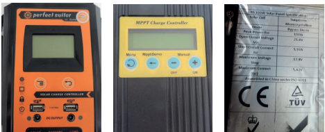
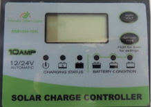
I have tested this and can confirm that just changing the controller increased the current from 5a to 7a. If as I have, you have more than one solar panel (I use 3) and they are all slightly different outputs, the MPPT sorts out the balance even when one is in shade and 2 are in sun. The MPPT controller is as you would expect, more complex and expensive up to around £70. This may mean that some suppliers may claim to be MPPT when they are not. I was fooled by this but claimed back from the seller as the description was clearly false. I have some photographs of the various types; PWM 10 amp, fake MPPT (plenty of usb points on it!) and a real MPPT 10 amp unit. So check that you get the correct item!
I have 2 panels on the roof of my Westy and when raised the angle is quite close to optimum. I also have
one on the front luggage rack so I can get power even as the sun passes over. I have this arrangement
to support not only lights and water pump, but the compressor fridge that is of course run 24/7. I would

not want to run out of ice for our G&T’s after all!
Malcolm

Ask The Mechanic – 168 – Replacing the brake master cylinder

For this installment of The mechanic, we welcome a submission from Jonathan Bruton. You may recall his submission for issue TT166 concerning brake overhaul, this is the second chapter of that story.
Not long after I had put my tools away and given
myself a smug pat on the back for having successfully
installed new callipers and discs on the front wheels
of Mortimer Henderson (TT Issue 166), my ’73 Bay, I
happened to see a Facebook post from Nick Gillott
to the effect that the master cylinder also needed
replacing at regular intervals. The master cylinder, as
its name suggests, pushes brake fluid through the
lines to the slave cylinders at the wheels when you
hit the brake pedal, operating the brakes through
hydraulic pressure.
Anyway, I tried to ignore this unwelcome piece of
advice but could no longer do so when it became
obvious that the pedal was getting spongier by the
journey; when I finally got around to checking the
level of the reservoir, it had gone down quite sharply,
and I could see brake fluid dripping out of the hole
in the front pan beneath the pedal assemblies. So,
action was clearly needed.


Once the pan was removed, the first thing to do
was to locate the cylinder, which I had never looked
for or seen. As you would expect, it is bolted to the
frame beneath the brake pedal assembly, and the
brake pedal rod fits into it through a rubber boot,
which itself fits through a hole in the frame and is
designed to keep out dirt and debris. Two brake lines
lead away from it – one to a T-piece which then feeds
the front wheel brake assemblies, and the other to a
pressure equaliser bolted to the offside edge of the
frame, which feeds the rear brakes.
The main fluid reservoir crouches on it piggyback style and is attached via two nozzles that run
through rubber grommets. Finally, the brake light
switch screws in at the back (on my replacement
cylinder, there were two holes for the switch, and
a video I watched for the same job on an early Bay
showed two brake light switches, for reasons I’m not
clear about).


At first glance it was immediately apparent that all
was indeed not well. The boot was in shreds, and the
assembly was clearly leaking, presumably because
dirt had penetrated the seal. But replacing it looked
pretty straight forward, and I naively anticipated that
it’d be done in a single afternoon! It really needed
to be as well, because we only have one parking
space, which has the charger for our main car, a fully
electric Nissan Leaf, which we can’t use if it’s blocked
by a hulking great immobilised van! This has been a
point of friction between me and my long-suffering
partner in the past, but I blithely assured her that
there would be minimal disruption.
In this optimistic spirit, I ordered the replacement
part from JK and offered it up to make sure it was the
same as the one on the van, which it was. So now it
was a matter of whipping off the two 13 mm nuts
holding it on, unplugging the brake light switch and
undoing the two brake pipes, emptying the fluid
reservoir in the process. Yeah, right!
For some reason best known to themselves, VW had
opted for nuts and bolts rather than studs to hold
the cylinder on. Which would inevitably mean that
the whole bolt would just start rotating. Which both
of them did. With one of them, I could get a wrench
on the bolt head and get the nut off no problem.
The other one, however, was conveniently located
in a recess, making it impossible to access with a
wrench, so there was no way to hold the bolt still. In
the end I had to resort to a mechanical nut splitter to
remove the offending nut. With a bit of persuasion
by hammer, I was then able to loosen the cylinder
and start moving it backwards.
The next issue was with the two brake pipes. When
new, of course, the nut rotates freely around the
pipe. After 47 years of exposure to God knows what,
however, muck and corrosion do their worst, and
the nut sticks fast to the pipe. Once I’d been forced
to buy a new 11 mm wrench (inevitably, the only
wrench missing from my set was the one I needed), I
ended up doing what the guy in the early Bay video
had earnestly warned me I really didn’t want to do,
which was to shear both of the nuts right off. After
a few seconds of panic, however, I realised that both
sections of pipe were relatively short and could
easily be unbolted from the other end: at the abovementioned T-junction and the pressure equaliser.


Perhaps this kind of damage is more consequential
in an early Bay. Whatever, I then relaxed and let the
brake fluid drain out through the fractured pipe ends
into a handy receptacle below. My advice would be
to assume that these pipes are going to be toast and
simply order replacements when you order a new
cylinder; it’s no big deal.
So, having broken both pipes and removed the
retaining bolts, I took the cap off the brake light
switch and pulled the cylinder out, complete with
fluid reservoir. Now, this is attached to the secondary
reservoir in the cab by a length of plastic pipe held
in with two plastic hose clips, themselves secured by
two tiny cross-headed screws. These are a bit pesky
to reach, but I got the lower one out easily enough,
assuming I wouldn’t need to move the uppermost
one, and removed the whole assembly.
The reservoir plugs into the cylinder in two places, as
I said above, and it’s a very tight fit – which it needs
to be – so I had to use a screwdriver to exert some
leverage to get it off. No problem there. It was in
good nick, with no cracks or splits, so I could simply
reuse it. The new cylinder comes with the sealing
grommets, so you just have to use some elbow
grease to push the reservoir on. Just make sure you
get it the right way round! Once it was all in place,
I bolted the cylinder in place, having replaced both
nuts and bolts.
Annoyingly, I missed the delivery driver when he
came with the new brake pipes the following day.
That day being Friday, it meant that the van would
have to sit on the space until at least Monday. I
averted a charging-related roasting by offering to
take the Leaf up to the nearest charging station,
so harmony was restored. Monday came and
the eagerly awaited pipes with it. As they have a
diameter of 3/16 “, they’re very easy to bend without
kinking. The only issue here was that the length of
pipe that went to the pressure equaliser was only
just long enough, meaning that I had to carefully
plan the shortest possible distance.
Having removed the old pipes, it was then something
of an epic task to get the nuts to engage with the
threads at both ends – I would get one in place, only
to find that the other end simply wouldn’t oblige. In
the end, I had to loosen the cylinder body again, and,
after rather a lot of swearing, the nuts were finally in
place, and I could reattach the cylinder to the frame
and reinsert the brake pedal rod into the boot.
Surely it would now just be a simple matter of
reattaching the plastic pipe to the bottom reservoir,
refilling it with fresh fluid, and bleeding the brakes.
Ahem. Not quite.
To start with, there was the second hole for the
missing brake light switch. Not much point putting
fluid in for it simply to run out again through a
great big hole. As automotive bolt threads seem to

be narrower than their DIY counterparts, my local
hardware store was unable to provide a suitable
blank. Happily, they directed me to a garage round
the corner, and the chap there fished around until
he found a bolt with a nipple, which looked like it
came from a carburettor assembly, that had the right
thread and would do the job. Now, it would surely
all work.
With great lightness of heart, I tightened everything
up and started to refill the cab reservoir – only
to discover that the fluid was dripping out at the
bottom almost as fast as it was going in! Yes – it
was the hose. Leaking at both ends. Meaning that,
to investigate, I’d also have to undo the topmost
clamp, which was virtually impossible to reach
from underneath. Filing that away as a problem for
later, I replaced the pathetic little plastic clip at the
bottom end of the hose – where it joined the lower
reservoir – with a proper jubilee clip and tightened
it nice and snug. I then had the blindingly obvious
realisation that it would surely be possible to undo
the reservoir in the cab and lift it out to get access
to the clamp immediately below it. But I couldn’t see
how to release the reservoir. Fortunately, the Samba
came to the rescue, and I was soon undoing the two
little screws that held it in, which enabled me to lift
up the reservoir and shed light on the problem.
Sure enough, the hose at the top end was split, so I
trimmed it and replaced the plastic clip with another
metal pipe clamp. I also realised that the nozzle (I
can’t think of the proper word for the protruding part
the clamp attaches to!) and was supposed to have a
plastic sleeve around it to aid the seal, but this sleeve
was missing from both ends, so all I could do was
make sure the clamps were located on the slight
bulge in the nozzle and done up nice and tight.
And then – glory be! – the leak was finally sorted!
I filled her up and fetched my handy little Draper oneman bleeding kit, which is a bottle with a one-way
plastic hose that fits snugly over the bleed nipple
and doesn’t permit any backflow. When you’re lying
under the van, you can operate the brake pedal from
underneath and watch as the air bubbles shoot out
of the bleed nipple and disappear into the bottle,
to be replaced by a lovely golden bar of brake fluid,
which is a fine sight.
So, there it was. All done. Except that I couldn’t find
the cab fluid reservoir cap. Anywhere. I’m sure many
of you will know what it’s like not to be able to find
the tool you’ve just put down and to have to spend
ten minutes searching for it until you find it in your
pocket or somewhere. Anyway, as my frustration
and incredulity increased, I resorted to rummaging
through the recycling until I found the top of a
squash bottle which could be made to fit. Better
than nothing! Anyway, I could finally triumphantly
drive the bus off the parking space and swap it for
the Leaf, which I plugged in, thereby ensuring that
domestic harmony would continue without a ripple.
And then, there was the reservoir cap. Perched
on top of a wheelie bin, where I’d left it. Laughing
at me.
Jonathan Bruton

Renewing the front brakes on my ’73 Bay, Mortimer Henderson

By Jonathan Bruton

CAVEAT: brakes are obviously safety-critical components, so only attempt this job if you are confident that you can do so safely! This is a personal account of a process and not an exhaustive set of instructions; the author cannot be held liable for any injury arising from accidents caused by a failure to carry out safety-relevant tasks properly.

Some while ago, in that pre-Covid world in which we could drive places (remember that?), I started to become aware of a tell-tale grinding noise coming from Mortimer’s nearside front wheel. There still seemed to be adequate braking power, nor was the van pulling particularly in either direction when I applied the brakes, so I wasn’t unduly concerned. But I thought I’d take advantage of the lockdown to jack him up, whip off the wheels and take a look at the callipers and brake discs.

The old caliper

You can imagine my horror when I saw that, in the first assembly I looked at on the nearside, the calliper pistons were frozen in such a way that the brake pads must have been forced up against the disc surface. The pistons normally only protrude slightly from the inner surfaces of the calliper, allowing enough space to snugly fit the two pads with a tiny bit of clearance. But as  you can see on the picture, the dirt seals – concertina boots that should move in and out with the piston and protect it from contamination – had long since perished and the pistons had accordingly seized up in extended position. On closer inspection, it also became apparent that there was zero friction material left on either pad(!) – what I was hearing was metal on metal. Whatever braking performance there may once have been was obviously a thing of the distant past! The disc surface was as scored and uneven as you would expect under those circumstances, and the disc was obviously beyond redemption. Things were a little better on the other side, with some wear left on the pads – although the fact that van wasn’t pulling to the right suggests that that brake wasn’t functional either. I toyed with the idea of trying a rebuild but, when it became evident that there was no way I was going to get the bleed valves free, I thought I might as well save myself a lot of bother by buying new callipers for both wheels along with two new discs.

The worn brake pad

The first job, of course, was to get the old callipers off so I could remove the discs. This was relatively straightforward. I first had to undo the two 17mm retaining bolts on the inside of the assembly. I then used a pin punch to knock out the two pins that hold the retaining spring in place before tugging out the old pads. It was then a question of pulling out the clip that holds the hose in place and removing the whole assembly from the disc, being careful not to place undue strain on the metal brake pipe that attaches to the calliper. I also needed to bear in mind that the topmost bolt has an unthreaded section on the shank closest to the screw head. The nuts were pretty tight, however, and I needed a torque wrench to get them off. According to the BUSARU guy, the torque is about 110 lbs.

The top bolt

The tricky part in getting the discs off was removing the two button head Allen bolts. Stopping the drum from rotating was an issue until I had the brainwave of clamping the disc to the backing plate. I managed to free up one bolt on each side by conventional means but soon found myself in danger (of course!) of irredeemably rounding off the holes in the other two in my desperate attempts to get them to budge. I even resorted to cutting a groove into one of them (and the surrounding metal) with a grinder to create a slot for a screwdriver. But nothing could persuade it to move! A quick appeal to the Samba revealed a range of opinions on the subject, from just drilling the heads off (the logic being that the thing was securely held in place by the wheel anyway and wasn’t going to go anywhere) to using an impact driver. I like to do things properly if I possibly can, so it was off to eBay to get myself an impact driver (can’t believe I’ve never owned one!). And, hey presto, a couple of whacks on each side got the troublesome little critters out. I took a quick look at the condition of the bearings, which seemed fine and well-greased, so I left them alone. I then fitted the shiny new discs to both sides.

The shiny new disc

The next job was to disconnect the old callipers from the brake lines. Now, as the brakes are safety-critical parts, I’d always shied away from doing anything that would involve having to refill and bleed the fluid. But, having watched a number of YouTube videos on the subject, I concluded that I had nothing to fear but fear itself and went ahead. It would have been a good idea to apply some WD40 to the nuts first, though: on one side, the pipe started to twist with the nut (which should normally spin freely around it), which promptly sheared off. So it was back to Just Kampers for a new 24-cm brake pipe (I swear I’m keeping that company afloat single-handed at the moment!).

Offering the caliper to the disk

With the old units out of the way, it was just a matter of fixing the new ones in place, torqueing up the bolts, and sliding in the new brake pads and backing plates, having first applied some anti-squeal gunk to both sides of the plates. Once they were both in, it was the turn of the retaining spring and the two pins (here I reused the old ones because the new pins supplied with the kits resisted my efforts to tap them into the holes). I used a pin punch and hammer to tap them home.

The new caliper in place

Then it was just a question of bleeding the brakes, replacing the wheels and venturing out for a short road test (keeping an eye out for the police – strange times!). Job done!

Kit acquired for the job:

From JK:

Front brake kit (discs, pads, fixings) £94.75
Calliper (nearside) £99.75
Calliper (offside) £99.75
Brake disc screws: £21.00
Morris brake fluid (1 litre) £11.00
Front brake pipe £15.00

From Amazon:
Impact driver £23.94
Holts brake cleaner £5.25
Ceratec anti-squeal paste £3.30
Starrett pin punch £4.39

Total for job: £378.13

Fuel hoses

Anyone with a vehicle knows that fuel is really rather flammable. This is why you do not smoke at a fuel station. Anyone owning or driving an old vehicle should be equally careful with the state of the fuel “line”.

From the tank to the engine, the fuel is permanently sitting in metal pipe, plastic pipe and rubber pipe. There is no off switch, so if this ruptures, you are dumping the entire contents onto the ground, so from a financial point of view it is a sensible idea to ensure this is all in good order. From a heartache perspective, it is imperative as well.

You do not want your pride and joy catching fire due to a leaking pipe spraying fuel onto something very hot in the engine bay.

Taking the Type 1 engine as an example, there are multiple systems in place as primitive fuel emissions systems.

The U shaped pipe number 9 is the one that you can see on the roof of the engine bay in a Bay window just above the number plate.

Red pipe numbered 24 needs a long arm and can be reached by putting your left hand up past the rear light cluster up the side of the bus and is quite a tricky little one to replace. If you can smell fuel always, especially if you sniff the air intake on the left side, that is often missing or perished.

The ones next to the fuel tank in the picture by green 24 are all behind the fuel tank firewall and need the engine to be removed.

My local VW mechanic recommends replacing all of the rubber components at least every 3 years and last time , we found that blue 24 in the middle of the picture on the pipe heading to the right was actually disconnected, causing fuel to spill over the top of the tank when turning right with a full tank! We had a clean section of tank and a lucky escape.

In summary. Ensure that your fuel system is inspected regularly by a competent mechanic and relevant parts are changed. The new fuels have either Biodiesel or Ethanol in them, which are not good on modern rubber pipes.

Basic servicing of your air cooled vehicle

Step 1 Changing engine oil
Engine oils should be changed at 3000 mile intervals, to ensure that your engine doesn’t suffer from undue wear and tear. Some people even suggest that it should be changed every 2000 miles. If this seems a little extreme just think about how much it will cost to replace your engine should you have a catastrophic failure due to excessive engine wear! The actual oil change interval is up to you, but I wouldn’t recommend that you go more than 3000 miles. Always check you are using the recommended oil for your engine.

Step 2 Tyre pressures
It is important that your tyres are inflated to the right pressure. Your buses ride will be better and its road handling will be much improved, which also means that it will be safer. Check your tyre pressures at least every two weeks and always before a long journey. Make sure you know the correct tyre pressures for your model of VW Bus.

Step 3 Windscreen Washer bottle
The washer bottle on a VW Bus is located behind the front kick panel to the left of the steering column. The peculiar part of the set up is the fact that it needs compressed air to force the water from the bottle to the windscreen. You can attach a normal air line at your local garage and pressurize to 40psi. Warning, do not pressurize it any more than 40psi because you run the risk of blowing the pipes of the washer nozzles. It’s a lot of work to put them back on!

Step 4 Gearbox Oil
Although the gear box should only be changed every 30000 miles it may need topping up from time to time. The fill plug is located on the side of the gear box near to the clutch cable. The official documentation suggests you will need a 17mm Hex spanner, but mine seems to be 18mm! Use Hypoid EP80/90 gear oil and fill so the oil is level with the bottom of the hole. It is essential that you locate your bus on a flat surface when you perform this task.

Step 5 Spark plugs
Cleaning your spark plugs should be undertaken every 5000 miles or so. The electrode gap should be 0.7mm or 0.028in. You can clean the electrode with a little piece of emery cloth or a fine wet and dry. Personally I prefer to completely change my spark plugs every 10000 miles and check them every 5000 miles or so.

Step 6 Distributor Cap
When you replace or check your spark plugs it is necessary to inspect the condition of the distributor electrodes because they can become corroded. If so they can be cleaned or replaced depending on the level of corrosion.

Step 7 Rotor arm
The rotor arm (inside the distributor), should be checked, cleaned or replaced every 5000 miles or when you check the condition of your spark plugs. They are not expensive so I prefer to replace new for old on every service.

Step 8 Ignition points
The Ignition points should be checked every time you undertake the general electrical servicing outline above. The points gap should be 0.4mm or 0.016in and should be clean. If they are pitted or corroded in any way they will need replacing.

Step 9 Fan Belt
Check every time you look in the engine bay! Its easy. 10 – 15mm play is fine, anymore and you should adjust. There are some small shims that can be removed if the fan belt is too loose.

Step 10 Air filter (Oil Bath Type)
The air filter will need to be cleaned and the oil replaced every 5000 miles. Drain the old oil, clean and fill up with new engine oil. Make sure you dispose of your engine oil properly. Your local council will have an oil disposal unit.

Step 11 Fuel lines and hoses
Check the condition of your fuel lines every time you follow this service check list. If they are chapped in anyway replace them. Remember – no smoking! You can get very high quality steel lines if you prefer. Whilst you are doing this you can check the heater pipes for holes or badly fitting joints and repair if necessary. Having holes or bad joints will reduce your buses chance of keeping you warm.

Step 12 Brake fluid
Brake fluid should be checked and topped up periodically. The brake fluid reservoir can be found behind the front kick panel.

Step 13 Brake Pads
The brake pads can be checked very easily on a bus, although you will need to remove the wheels. To do this jack up the vehicle and remember to always use axle stands. You will be able to see if your pads need replacing, they should be at least 7mm thick.

Step 14 Axle
The axle will need to be greased every 5-7000 miles. There are multiple points that need greasing. These are the steering idler that is located in the middle of the axle and the four trailing arm bushes at the ends. So a grease gun will be a great buy!

Step 15 Clutch
Your clutch should be checked for play periodically and should have around 20mm play at the foot peddle. You should also grease the clutch cable periodically to help its ability to work efficiently and to stop it breaking because it gets stuck.

The engine battery

Prompted by a member called Robert who was asking, sharing in case it helps anyone else.

Robert had an issue with his starter battery and wanted to replace it but of course is space constrained in an older vehicle. His 72Ah battery was the right size, but how many Amp Hours do you need?

A standard 1.6 litre air cooled engine requires a starter motor such as the Power Lite one from JK. That one is a 1.4 kilowatt starter. Converting kilowatts to amps you need to change 1.4KW to 1,400 watts and then divide it by the voltage, in our case 12 volts.

1,400 / 12 = Around 120 amps.

For two litre engines, you will need a little more. For a customised engine, who knows?!

If you look at The battery charge quick reference guide you know that you do not wish to flatten the battery completely as that will break it. Ideally avoid going more than 30% depleted.

If you know that you never use more than a minute on the starter motor to get the engine into life, that is 1/60th of an hour. Running that 120 amp starter motor for an hour would be 120 amp hours, so 1/60th of that is 2 amp hours.

As long as you have no current leaks and are not sitting in your vehicle draining the battery with a stereo, a fridge, lighting or other circuits on the starter motor, as you can see, a minute to start the engine on a 1.6 litre air cooled engine will drain 2 amp hours out of your battery. Even the smallest and cheapest car batteries will cope with that, but for peace of mind, don’t buy the cheapest battery in the shop!

Metalworking – cutting bigger circles

Here is one that I did not know. I have drill bits that go from 1mm up to 10mm in 0.5mm increments. I needed to drill a 12mm hole in a panel that I had fabricated ready to take a grommet for a cable.

I checked in with a neighbour and he only had 10mm drill bit maximum as well, so I got online to order a 12mm and a 32mm one as well for another cable hole next to it.

Here is something called a hole cutter that comes as a pack of 3 allowing holes to be made in 2mm increments from 4mm up to 32mm. All 3 came in a little pouch for about £10.

And they worked so quickly I was rather surprised:

The 12mm hole on the right for the heater cable took about a second to cut from 10mm to 12mm. The one on the left needs the bigger cutter!

Inexpensive way of making lots of different sized holes!

Ageing your vehicle

If you have a Type Two, here is how to identify the age and type of your vehicle as it left the factory:

2 1 2 2 1 5 7 4 4

First digit – T2 (Bay window)

Second digit – Type of vehicle:

1 -Delivery / Panel van
2 – Microbus
3 – Kombi
4 – Microbus
5
6 – Pick up
7 – Crew cab

Third digit – The year (2 means 1972 and 9 means 1979 etc)

The rest is your individual serial number for the vehicle.